Bela: analogue vs audio
The differences explained
Summary: Advantages and Disadvantages
We discuss here the audio and analogue I/Os on the Bela cape in more depth, and examine the differences between them. To start with, the terms are a bit confusing: isn’t audio already an analogue signal? If they are all 16 bits and sampled at the same rate, then why would you choose to use one type over the other?
All the details are below, but let’s start with the brief summary. This table explains the specifications and relative merits of each type of input. In simplest terms, the audio I/Os give you better filtering against noise and aliasing at the cost of higher latency, while the analogue I/Os give you DC coupling and more flexibility with very low latency.
| Bits | Sample Rate (kHz) | Level | Coupling | Conversion latency | Internal aliasing filter? | |
| Audio In | 16 | 44.1 | +/- 1V (gain available) | AC | 0.39ms | yes |
| Audio Out | 16 | 44.1 | +/- 1V (gain available) | AC | 0.47ms | yes |
| Analog In | 16 | 22.05 x 8 44.1 x 4 88.2 x 2 | 0-4.096V | DC | < 10us | no |
| Analog Out | 16 | 22.05 x 8 44.1 x 4 88.2 x 2 | 0-5V | DC | < 10us | no |
The difference is that the audio I/Os are optimised specifically for the demands of audio, where the analogue I/Os are more general-purpose. The capelet will add the necessary circuitry to give you AC coupling and some filtering on the analogue I/Os, making those inputs and outputs usable as extra audio channels.
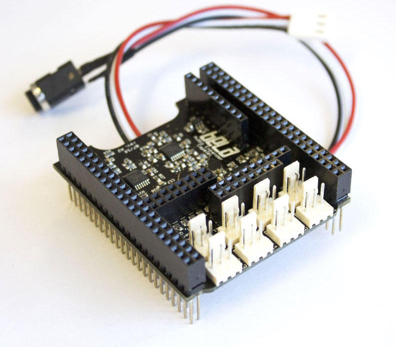
What’s on the Bela cape
The Bela cape has three chips that together handle the analogue and audio I/O. Let’s look at each of them in turn.
The Analogue Ins use an AD7699 ADC from Analog Devices. This part provides 8 inputs at 16 bits each. It’s what’s known as a SAR (successive approximation register) type converter. More on that later.
The Analogue Outs use an AD5668 DAC (digital-to-analogue converter) from Analog Devices. This part provides 8 outputs at 16 bits each. It is a string type converter. Again, more later.
The stereo Audio I/O uses a TLV320AIC3104 audio codec (coder-decoder) from Texas Instruments. Since audio is also a type of analogue signal, the codec contains within it an ADC and DAC for audio in and out, respectively. These provide 2 channels each at 16 bits*. Both ADC and DAC uses a sigma-delta type converter.
* The codec is actually capable of 24-bit conversion, but Bela runs it at 16 bits which reduces the amount of data that needs to be exchanged between PRU and CPU. Limitations on noise floor mean that 24-bit conversion wouldn’t make an audible difference anyway. A similar argument can be made for > 44kHz audio sample rates. Click here for an interesting discussion of hi-res audio formats.
Types of Converter
The sigma-delta converters used in the audio codec have quite different properties from the SAR ADC and the string DAC. Let’s look at these types in turn (skip to the next section if you just want the practical results!).
SAR ADC:
A successive approximation register ADC converts an analogue signal to digital by making a series of progressively closer estimates of its value over a relatively short period of time (in this case, 2 microseconds or less per sample). In principle, samples can be requested on any channel at any time, though only one of the 8 inputs can be actively under conversion at a time. Bela automatically samples each of the 8 channels in round-robin fashion, for a total of 22.05k per channel * 8 channels = 176.4ksps (i.e. 176,000 samples per second).
The advantage of the SAR ADC is that it’s very fast. The latency between requesting a conversion and getting the result is only a few microseconds. However, compared to sigma-delta parts, SAR ADCs are expensive (the AD7699 and AD5668 are by far the two most expensive parts on the Bela cape). There is also a subtle disadvantage in noise performance compared to sigma-delta conversion which we will explore below.
String DAC:
A string DAC is basically a long string of resistors all placed in series. To convert a digital signal into analogue, a digital switch selects a point along the string of resistors, which will produce the desired analogue voltage. This output is then buffered inside the chip so that it can drive an external load without weighing down the string of resistors and leading to inaccurate conversions.
The properties of the string DAC are very similar to the SAR ADC. Conversions can be requested on any channel at any time, and Bela sends signals to the DAC channels in round-robin fashion, at 22.05kHz per channel * 8 channels = 176.4ksps total. Like the SAR ADC, the conversion is very fast: the datasheet gives a typical settling time of 6 microseconds to within +/-2 LSB (least-significant bits) of its final value. Also like the SAR ADC, the string DAC is expensive and shares the same disadvantage in noise performance compared to the sigma-delta converter.
Sigma-Delta ADC/ADC:
Sigma-delta modulation is a clever and mathematically complex process that allows surprisingly cheap and simple converters to achieve excellent performance using oversampling. Oversampling means that even if the audio is nominally sampled at 44.1kHz, the converter inside is actually running at many times that (128x for the codec on the Bela cape).
A detailed description on how sigma-delta modulation works is beyond the scope of this post, but click here for a good explanation. For our purposes, there are several properties we care about:
Constant sample rate:
Where the other ADC and DAC could theoretically convert any signal at any time, sigma-delta audio conversion requires a constant sample rate to work properly. In practice, we are using constant sample rates for all the I/Os so this doesn’t make too much difference.
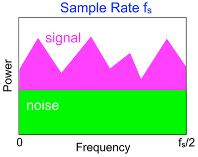
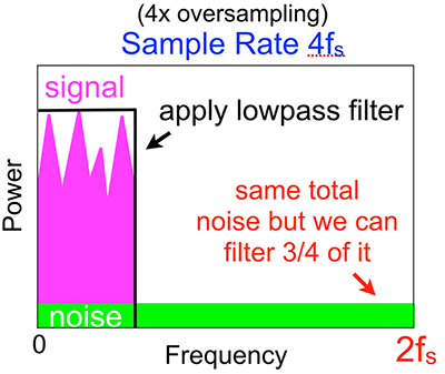
Oversampling with noise shaping:
This is by far the biggest win of sigma-delta modulation. The actual converter in a sigma-delta design often has far fewer bits than advertised – in fact it is typical to use a 1-bit converter! This would normally result in a large amount of quantisation noise (i.e. error from an imprecise estimate).
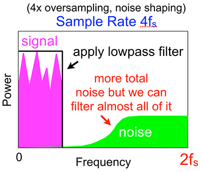
Oversampling with dithering can help reduce this effect, but sigma-delta converters do better using a clever feedback strategy to push all the noise up into the very high frequency ranges, well away from the normal audio range. This makes the noise very easy to filter out.
These diagrams illustrate the effect. In reality, the oversampling is much higher than 4x.
Coupling and Voltage Levels
Beyond the differences in noise performance and latency explained above, the audio and analogue I/Os differ in their coupling and voltage ranges.
The analogue I/O is DC-coupled. This means that in addition to audio-frequency signals, you can read and write constant (or very slowly changing) voltages. That makes these pins ideal for sensors like potentiometers and FSRs or other applications where the values change slowly.
By contrast, the audio I/O is AC-coupled. This means that only audio-frequency signals get through. There are good reasons to block DC signals for audio: we can’t hear them, and DC offsets can be damaging to speaker systems. On the inputs, if we don’t block DC offsets, we will lose part of the usable input range for no good reason. But the practical effect is that the audio converters are good for just that – audio – and not for general-purpose sensor use.
There’s also a difference in voltage range on these parts:
- Analogue out: 0 to 5V.
- Analogue in: 0 to 4.096V. The reason for the 4.096V range is to provide a stable voltage reference which allows a simple conversion from millivolts to digital values.
- Audio out: up to 2V peak-to-peak (i.e. -1V to +1V) at full volume, which can be programmatically reduced. The audio output is capable of driving headphones, where the analogue outputs are not. If you don’t want to use the built-in headphone amplifier, there are separate pads on the board with a line out signal (which also drives the speaker amps).
- Audio in: up to 2V peak-to-peak, but this can be programmatically increased using the on-chip PGA (programmable gain amplifier) which can provide up to 59.5dB of extra gain. But keep in mind this extra gain increases the analogue noise at the input too.
The Bela cape also has two speaker amplifiers (LM4876) which can drive 8 ohm speakers with up to 1.1W of power each. These amplifiers have differential outputs (i.e. both terminals of the speaker vary in voltage, and neither one is connected to ground), with each output swinging between 0 and 5V.
The Bela Audio Expander Capelet
We designed an Audio Expander Capelet which converts the analogue I/Os into extra audio inputs and outputs. With this capelet you can have up to 6 total audio inputs and 6 outputs, all sampled together at 44.1kHz. Alternatively, you can go up to 10 inputs and 10 outputs, with 8 of those sampled at 22.05kHz. This capelet is now available to buy from shop.bela.io.
To use the analogue I/Os as extra audio channels, then, we need to do three things. First, we need to provide AC coupling so we can send and receive bipolar (positive and negative) audio signals. Second, we need to add some extra analogue filtering to make up for the lack of onboard digital filtering in the SAR ADC and string DAC. Third, we need to match levels between the analogue and audio converters, which can be done in either hardware of software.
The capelet does all of these things. AC coupling is fairly easy: basically, just add a capacitor in series with the outputs, and a capacitor and a couple resistors for the inputs.
Filtering is less easy, mainly because the more aliasing we want to eliminate, the higher the order of filter we need. Higher-order filters in turn mean more parts, more board space, tighter component tolerances, and above all more cost. So we have to make a decision on the price/performance balance. For studio-quality applications, no embedded board can possibly match the performance of multi-thousand-dollar rack gear. But we want something that is good enough to use in a musical instrument with decent sound. We are still finalising the design of the audio capelet but the most likely scenario will be second-order filters on each input and output.
One final thing to do in software is to compensate for the differing latency between converters. If you want the signals to be exactly* aligned in time between analogue and audio I/Os, you need to add a bit of delay to the analogue converters to match the latency of the audio codec. Since this isn’t the right match for every application, we will make this a flag selectable at runtime in the Bela code.
* In fact there will always be at least a few microseconds of difference between each channel, since the ADC and DAC used on the analogue I/Os only convert one channel at a time. But alignment is possible within one sample period (22.6us) which is more than good enough for almost any audio application.