Controlling Motors with Bela
Using Bela to make things move
In this post we discuss controlling motors and other actuators with Bela. We’ll cover the best practices, circuits and code for making things move.
DC Motors and Bela
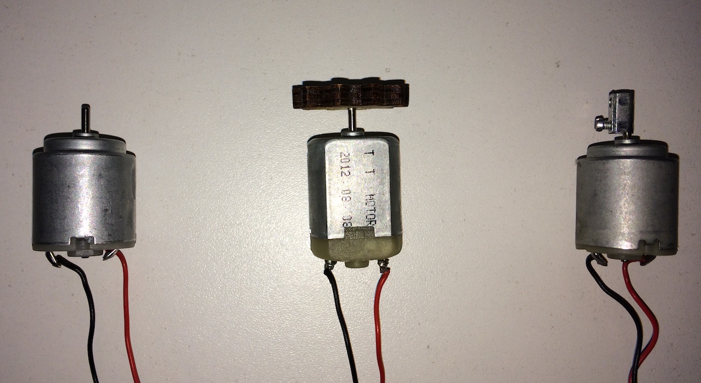
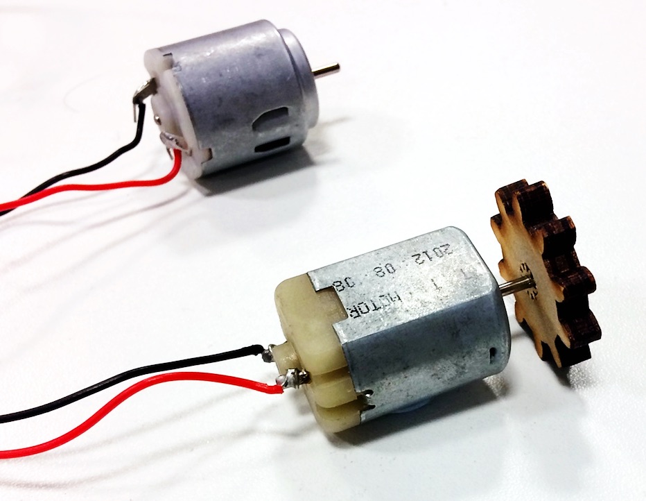
Small low-voltage DC motors (Direct-Current motors) like the ones below are common components that are used in all sorts of different hobbyist electronics projects. These are the simplest type of motors you can get: when a current is applied to the terminals of the motor it will spin, reversing power and ground on the terminals will make it spin in the other direction.
Motors are current hunger components and many motors will require more current than the Bela board can supply through its pins by default (limited to 250mA). With the small DC motors that are shown above and that are common to find in robotics or Arduino starter kits it is possible for the board to provide enough current to drive the motor. Below there are three approaches to controlling motors with Bela, each with their own circuit diagram and explanation.
A note of warning before we proceed
There a few important things to note when working with motors and Bela:
- When controlling motors or solenoids a flyback diode in the circuit is essential to protect the board from voltage spikes.
- No voltage higher than 3.3V should go into the Bela digital I/O. Failing to do so can make your Bela board unusable.
Hardware
Components
- DC motor or Solenoid.
- Diode (e.g.: 1n4007).
- 1K Ohm Resistor.
- NPN BJT (or MOSFET) transistor with high enough collector (or drain) current and adequate power dissipation capabilities. A TIP31AG would work for most purposes when handling small motors.
Using a transistor to amplify the current
Motors, solenoids and other types of actuators generally require a large current to work. The digital pins on the Bela board only can supply a maximum of 6mA, so they are not suitable to drive a motor directly. We therefore need to include a transistor (BJT or MOSFET) in our circuit that acts like a current amplifier. This way a small current provided by Bela’s digital pins and connected to the transistor base can be used to switch on and off a larger current, running through the collector of the transistor and the motor. You can also choose to use MOSFETs which are more efficient and do not require any current from the Bela pin. You need to find a MOSFET with a Vgs (gate-to-source voltage) of less than 3.3V to ensure that the Bela digital output reliably switches it on.
When picking your power transistor, the most important specs to consider are the collector (or drain) current, the collector-emitter voltage and the power dissipation capabilities. The datasheet for the TIP31AG shows that it can handle up to 60V of collector-emitter voltage (allowing to use an external power supply up to 60V), and up to 3A of current, to drive powerful motors. Additionally, it can handle up to 2W of power dissipation (or more, with a heatsink), so it can easily be used for controlling motors using PWM. All of these characteristics make it more than suitable to drive small DC motors like the ones in the figure (or even more powerful ones), and it can be a good starting point for your experiments.
Just remember, if later on you move to a larger motor, which draws more current, or requires a higher voltage external power supply, to always check the specs of the power transistor in use to make sure it is capable of handling the currents and voltages at play, and fit it with a heatsink if needed. Failure to do so may lead to a failure of the transistor itself, the power supply and/or the Bela board!
Flyback (or freewheeling) diode
When a motor stops spinning it is possible that it creates a voltage spike because of its momentum. If this happens, the voltage pulse generated (known as flyback) will try and find the most direct route to ground. This route could be back towards the Bela board which we don’t want to happen and so we need to put a protection diode in place to block the current from reaching the pins of the Bela board.
Software
Switching a motor on and off with a transistor
The simplest way to control a motor is by using one of Bela’s digital outputs. This is connected to the base of the transistor and can switch the larger current of the transistor on and off. This results in the motor spinning when the digital output is HIGH, and stopping when the pin is set to LOW. If this is all you need to do then you can skip straight to the circuit diagrams section. If, however, you want to control the speed of the motor then you need to use a more sophisticated technique known as Pulse Width Modulation.
Pulse Width Modulation for variable speed
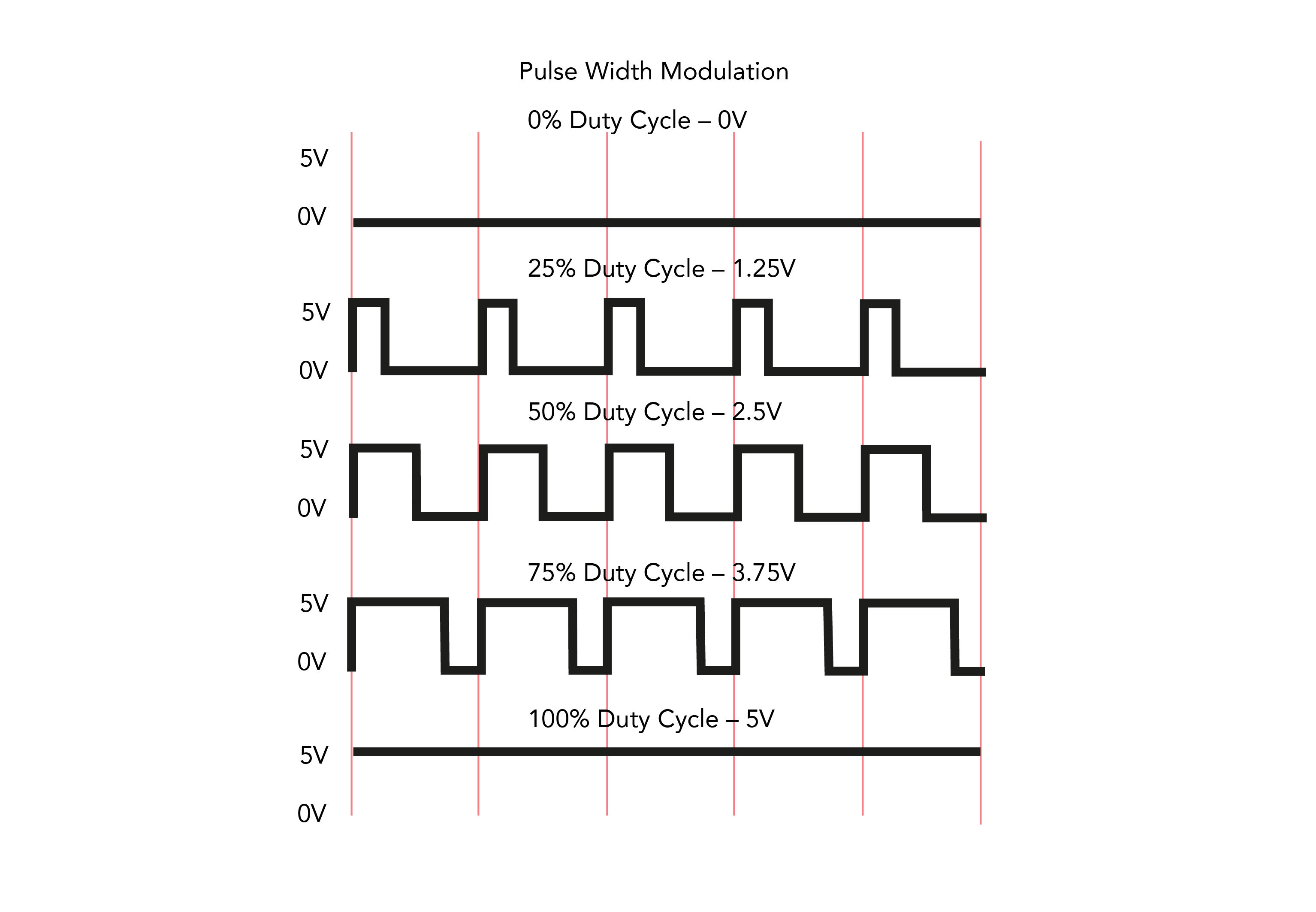
The best way to drive motors is using Pulse Width Modulation (PWM) which is a technique of switching a digital output pin ON and OFF at a certain frequency and with a set duty cycle (proportion of ON time to the overall period) to simulate a true analog voltage. This signal is a pulse wave where the width of the pulse is adjustable. If the frequency of the PWM signal is within a suitable range (e.g.: around 1000Hz - 5000Hz), then the motor effectively sees the PWM input as if it was an analog signal with a voltage proportional to the duty cycle. So, with a PWM signal oscillating between 0 and 5V, a duty cycle of 50% will be equivalent to a 2.5V analog signal, 25% as 1.25V, 75% as 3.75V etc.
The main advantage of using a PWM signal instead of an analog one is that the transistor driving the motor is much more efficient when it spends most of the time in the full ON or full OFF state, than if it were to be in an intermediate state, therefore it dissipates less heat. Additionally, it’s often much easier to switch a pin from HIGH to LOW than it is to output a true analog voltage. Bela is actually capable of generating a true analog voltage, using the on-board DAC, but most other devices are not.
In these examples we are using PWM because it’s the most common technique to drive DC motors in automation and robotics.
The code
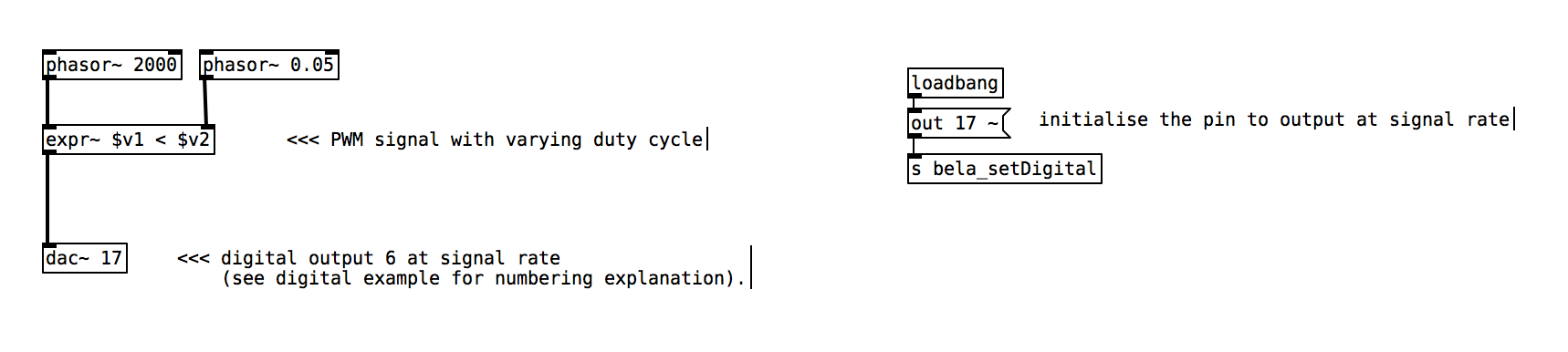
You can download a couple of code examples in Pure Data here. In this patch we are creating a pulse width modulation signal by using two objects: [phasor~] which generates a ramp signal that goes from 0 to 1 at a given frequency and [expr~ $v1 < 0.5] which checks if the incoming signal is less than 0.5 and outputs a 1 if this is true and a 0 if this is false. This results in a PWM signal that has a duty cycle of 50% and which looks similar to a square wave. We are using this signal to control a digital output at audio rate and switch its value from 0 to 1.
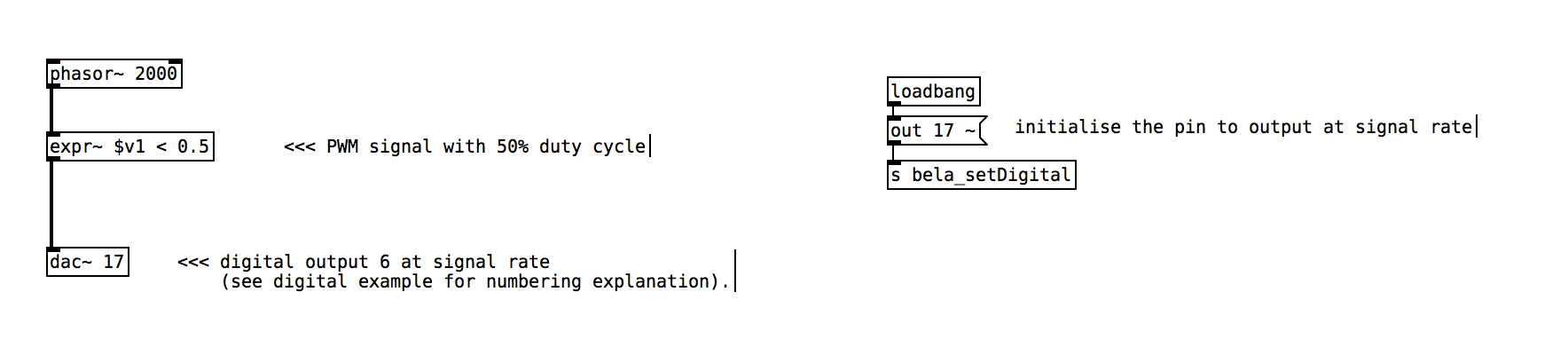
To vary the duty cycle of the PWM signal (and hence the speed of the motor) we simply want to vary the value that we are using in the less-than comparison. In the below example we are using a second ramp generator at a much lower frequency to continually vary the duty cycle of the PWM signal. We could equally use an analog input to directly set the duty cycle and hence the speed of the motor.
Circuit Diagrams
Powering motors from the onboard supply
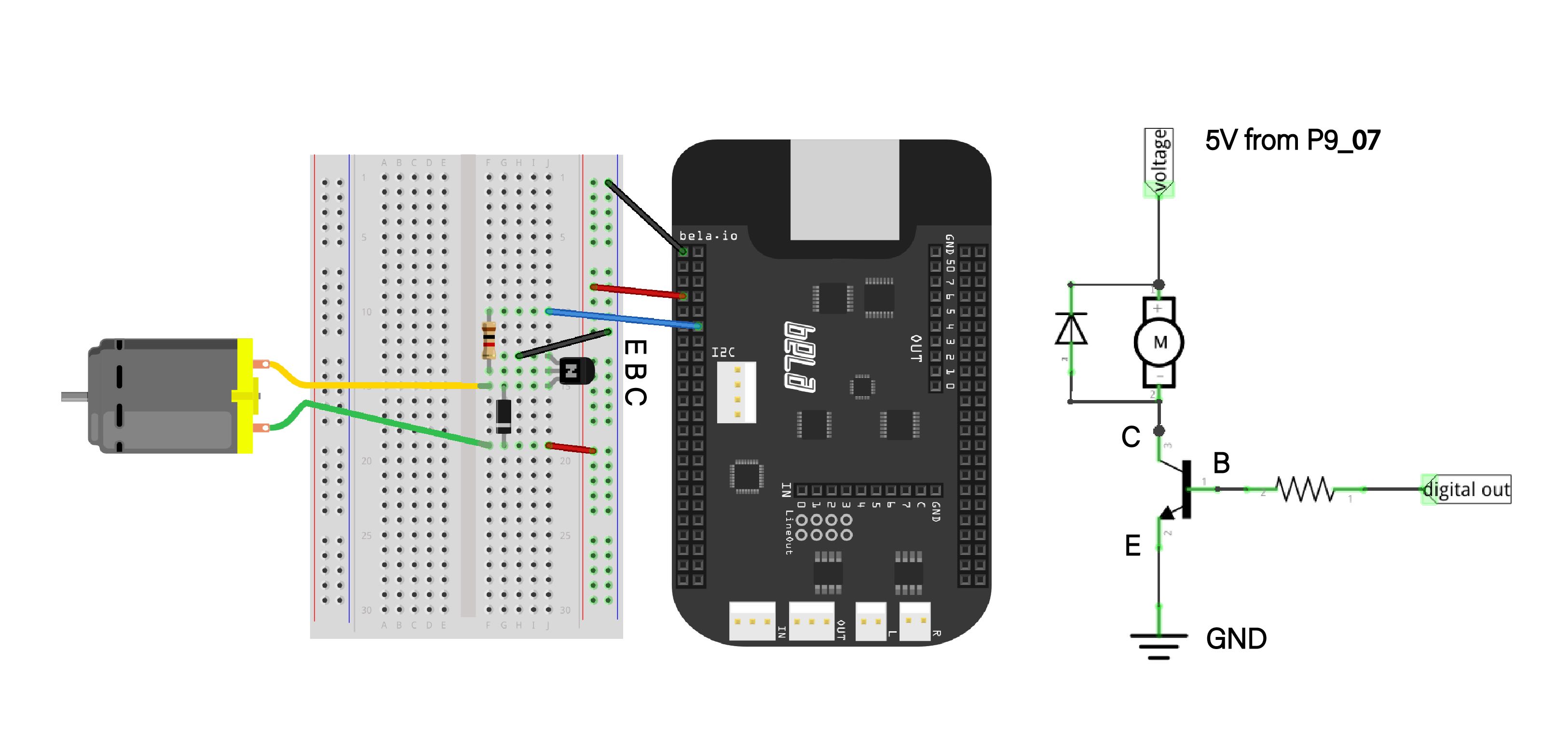
In this case we are powering the motors from the 5V supply that comes straight from the Beaglebone. This can be found on headers P9_07 and P9_08. With the above circuit you will be able to run the small hobbyist DC motors. The resistor in series with the Bela digital output pin serves to limit the current that the transitor receives at its base. There needs to be enough current going through to turn on the transistor.
Powering motors from the barrel jack supply
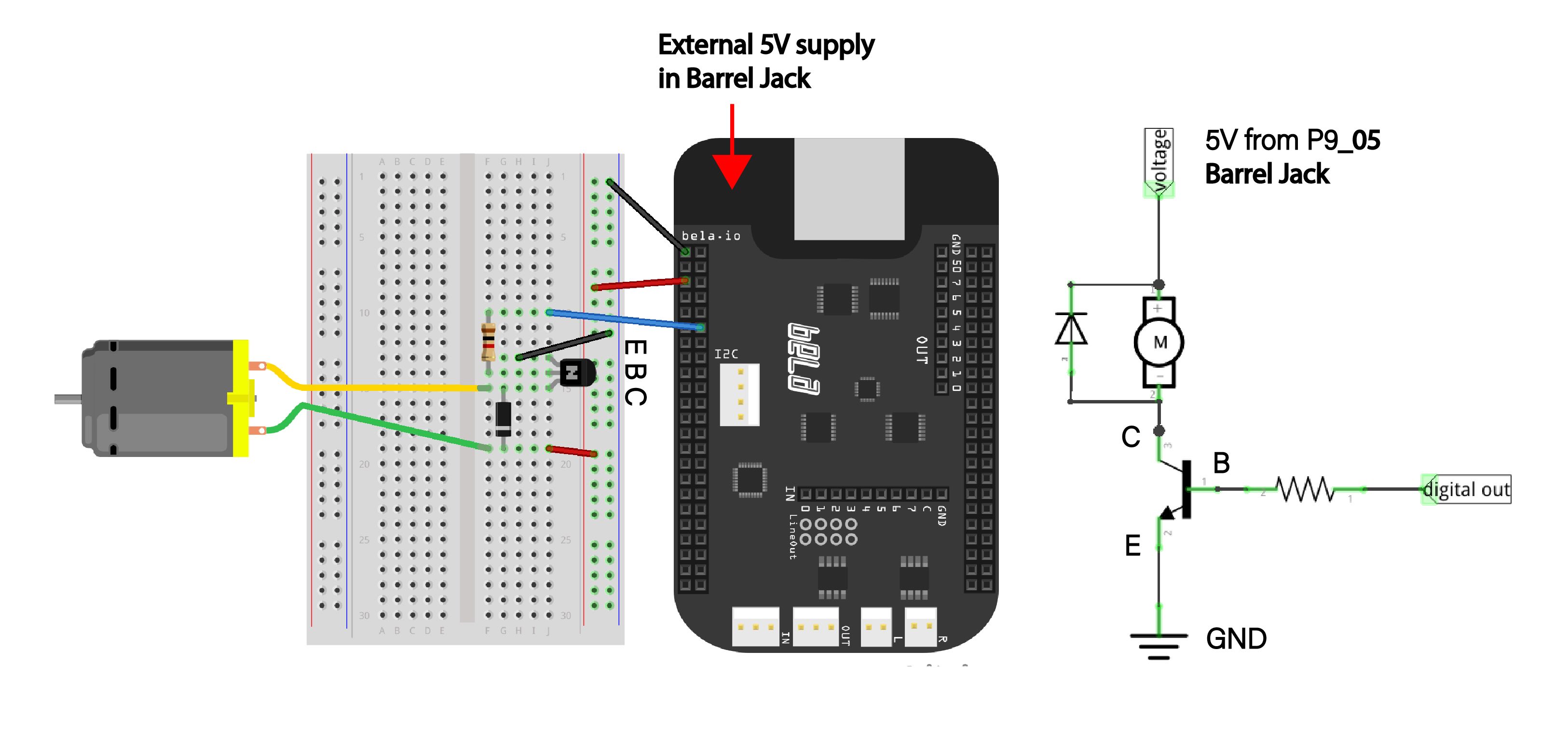
A better solution that runs less risk of resetting the board is to power the board via the barrel jack. This should be done with a 5V regulated supply. We commonly use barrel jack to USB connectors which we plug into the 5V rated plugs that are used for phone chargers.
The only difference between this circuit and the one before is that the 5V supply in now coming from pins P9_05 or P9_06. This 5V supply comes from the barrel jack and so you will be able to draw more current from here without worrying about the board powering off.
Powering motors from an external power supply
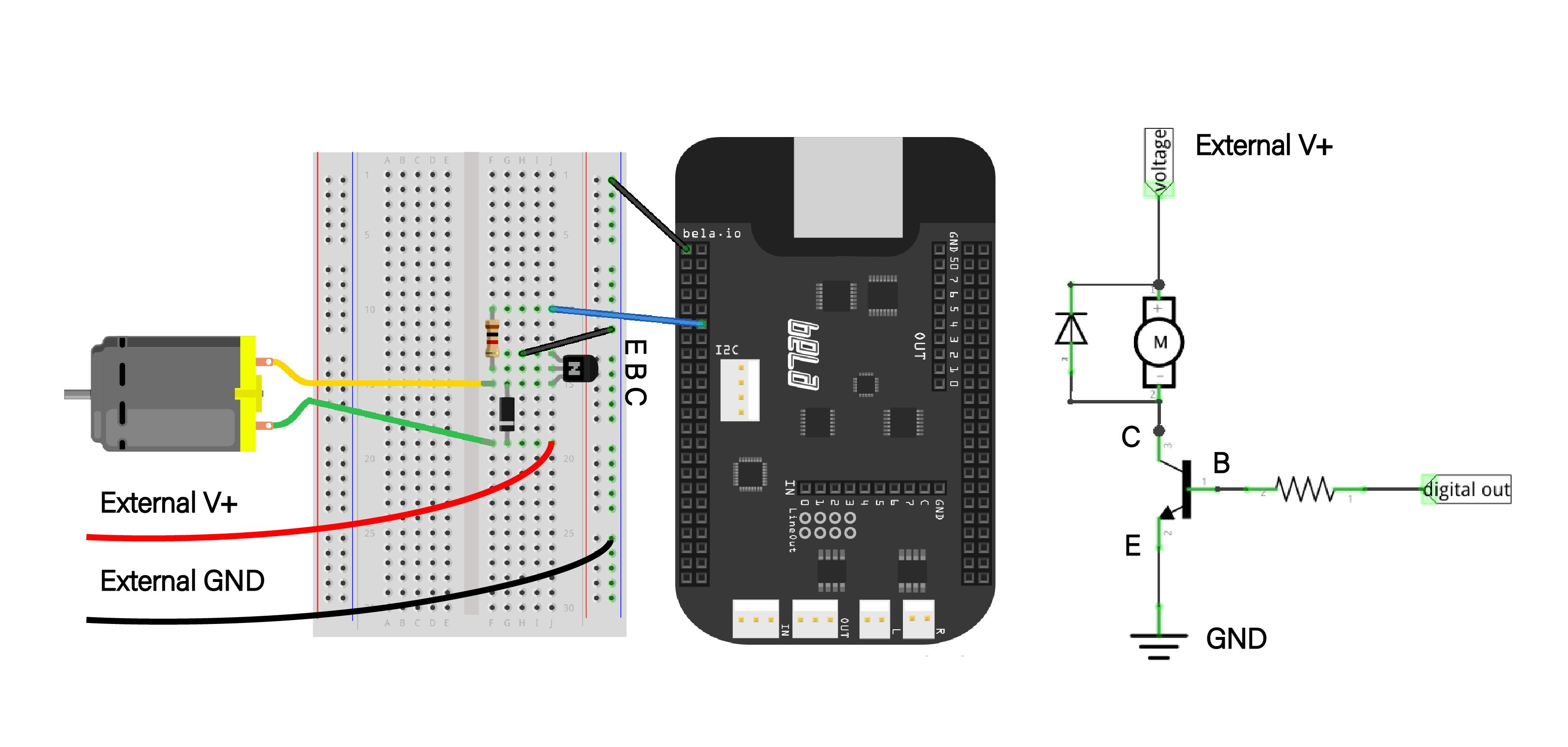
The third and most robust strategy for driving motors with Bela is to use an external power supply at the collector of the transistor that is controlled by the Bela pin at its base. This power supply can in principle be any DC voltage, meaning that you can use this configuration with many different types and sizes of DC motors. Because the external voltage does not connect to the Bela directly, but is switched on and off by the transistor, it is safe to use supply voltages higher than 5V. The ground of the power supply will need to be connected with the ground of Bela at the emitter of the transistor.
Project inspiration
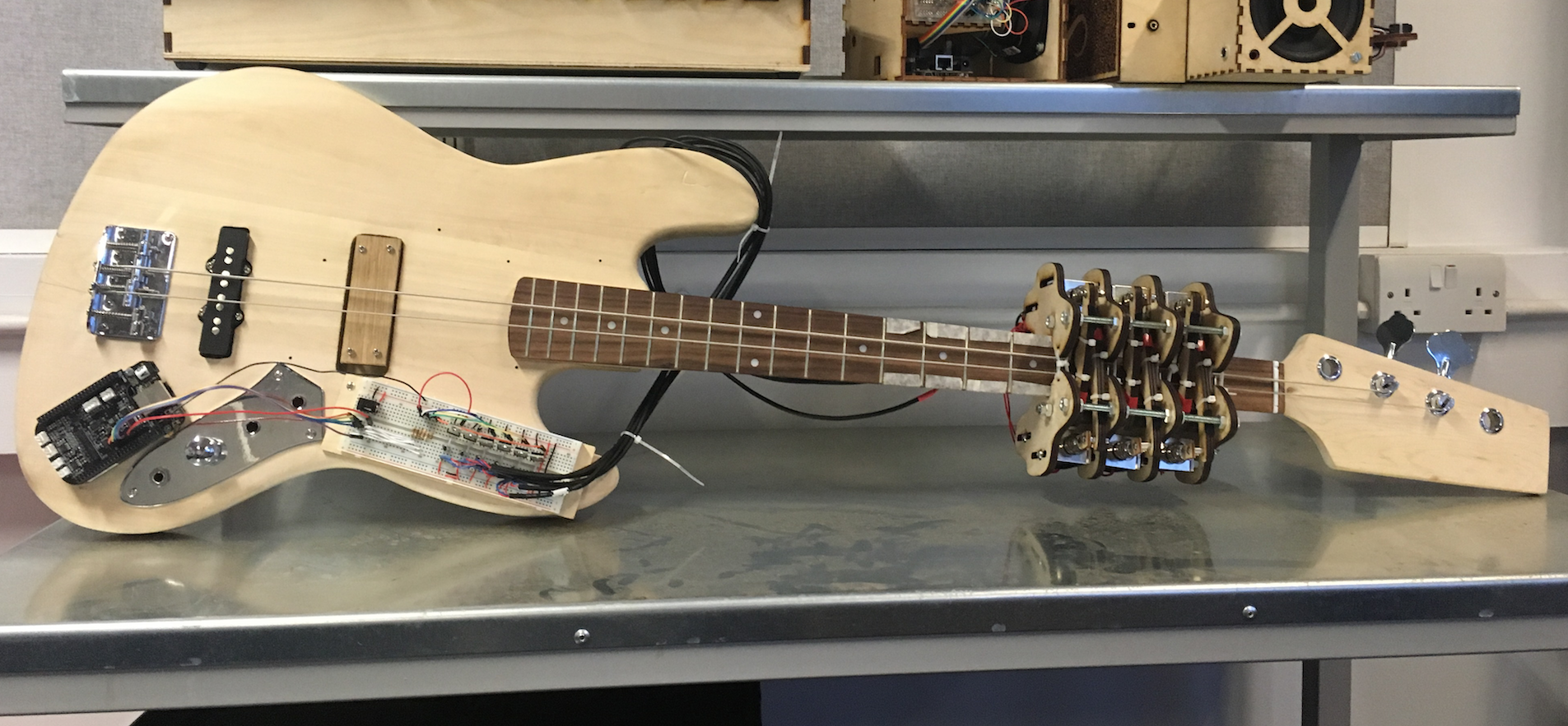
For some project inspiration have a look at making a one handed bass with Bela which uses a series of solenoids to fret a bass guitar, and Axis: a kinetic sculpture made with Bela which uses multiple stepper motors to create waves of movement and patterns related to the golden ratio.